← ESP8266 PCB Design – Create Your Own IoT Device! Getting started with esp8266 Wiring Diagram 24V Trolling Motor: Optimize Your Bass Boat Setup! What do l1 and l2 mean in electrical wiring? (explained →
If you are looking for Step by step design step-cone pulley in SOLIDWORKS - WizEdu you've came to the right place. We have 25 Pictures about Step by step design step-cone pulley in SOLIDWORKS - WizEdu like Dc Ac Power Inverter Schematic, Ac To Dc Schematic Diagram and also Quasi Resonant Flyback Step by Step Design Guide | ElectronicsBeliever. Here it is:
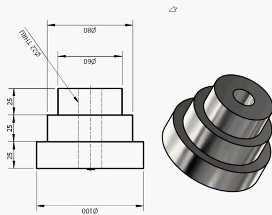
Step By Step Design Step-cone Pulley In SOLIDWORKS - WizEdu
 wizedu.com
Step by step design step-cone pulley in SOLIDWORKS - WizEdu
Dc To Ac Circuit Diagram Inverter
 circuitenginesylph123.z21.web.core.windows.net
Dc To Ac Circuit Diagram Inverter
Dc Ac Power Inverter Schematic
 dereglijeqw9guide.z14.web.core.windows.net
Dc Ac Power Inverter Schematic
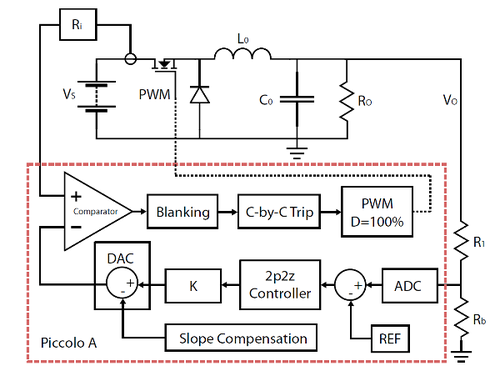
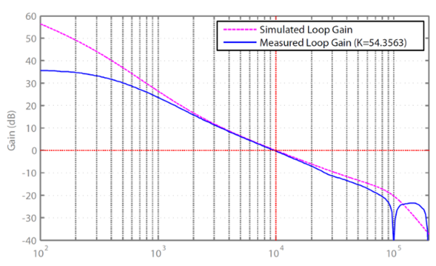
Digital Peak Current Mode Control Step-by-Step Design Guide
 www.omicron-lab.com
Digital Peak Current Mode Control Step-by-Step Design Guide
Step-by-Step Metal Stamping Design Guide: Tips For Engineers — Formero
 formero.com.au
Step-by-Step Metal Stamping Design Guide: Tips for Engineers — Formero
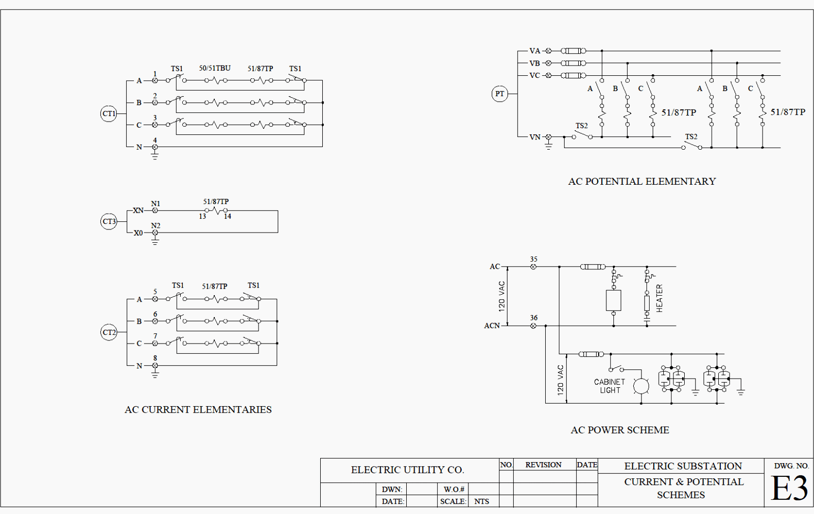
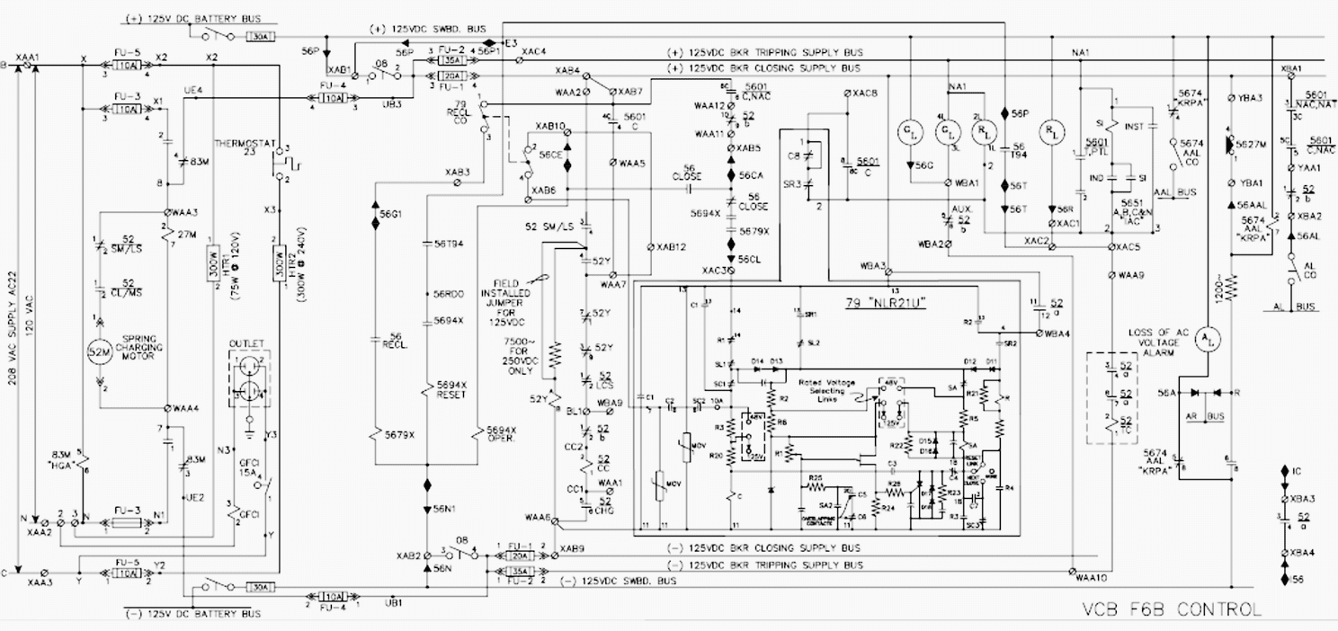
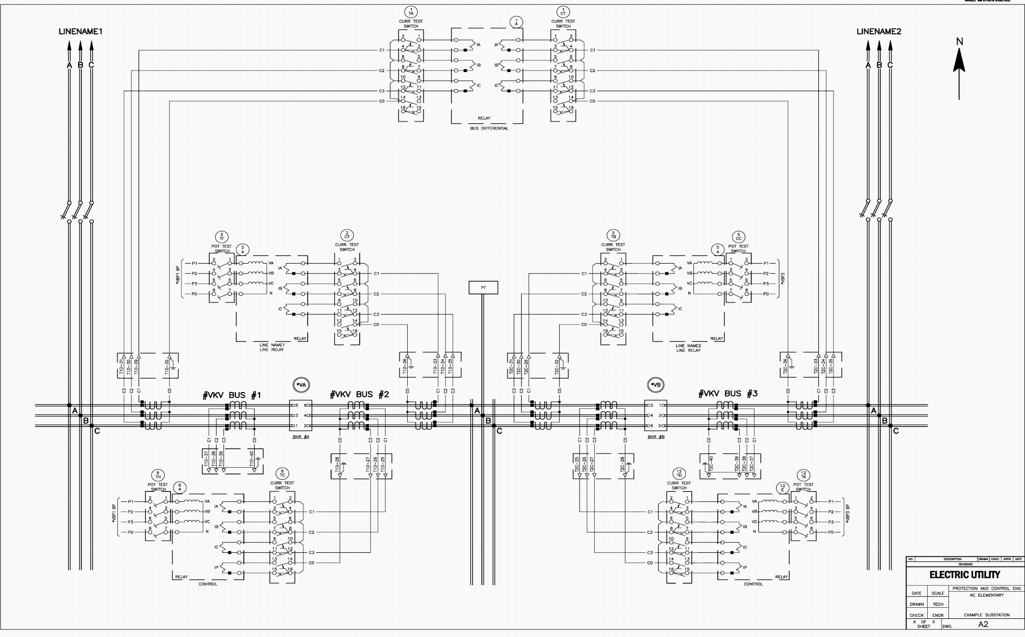
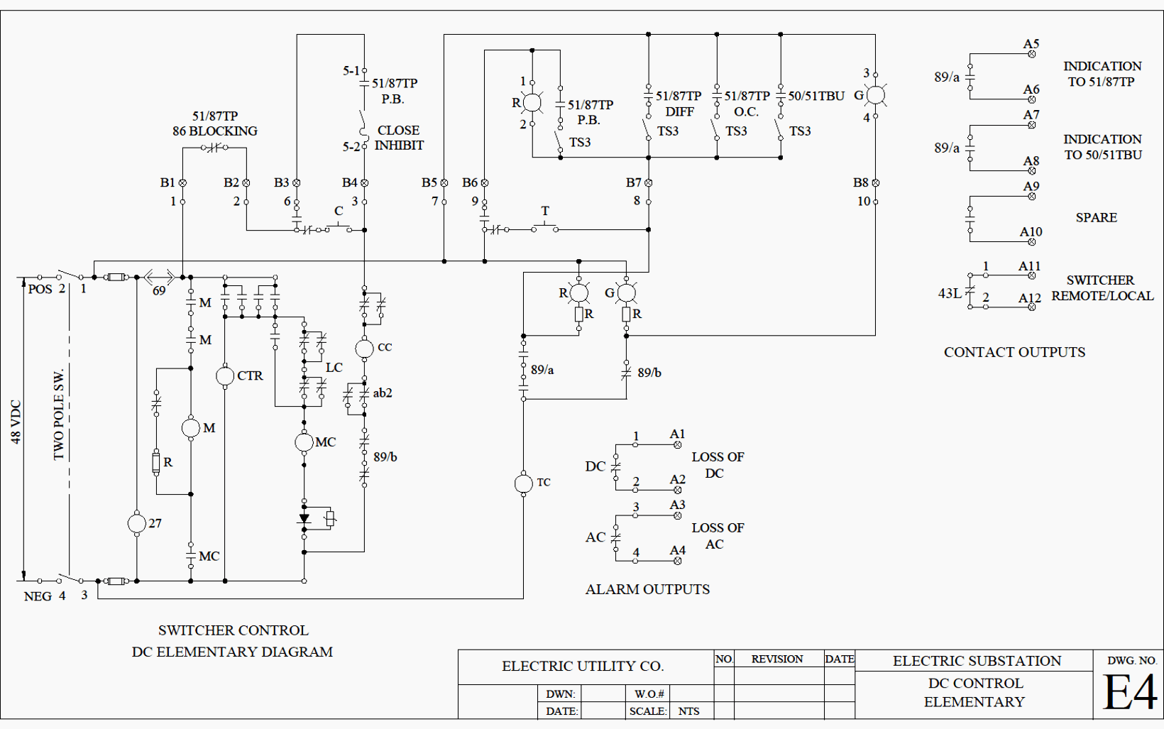
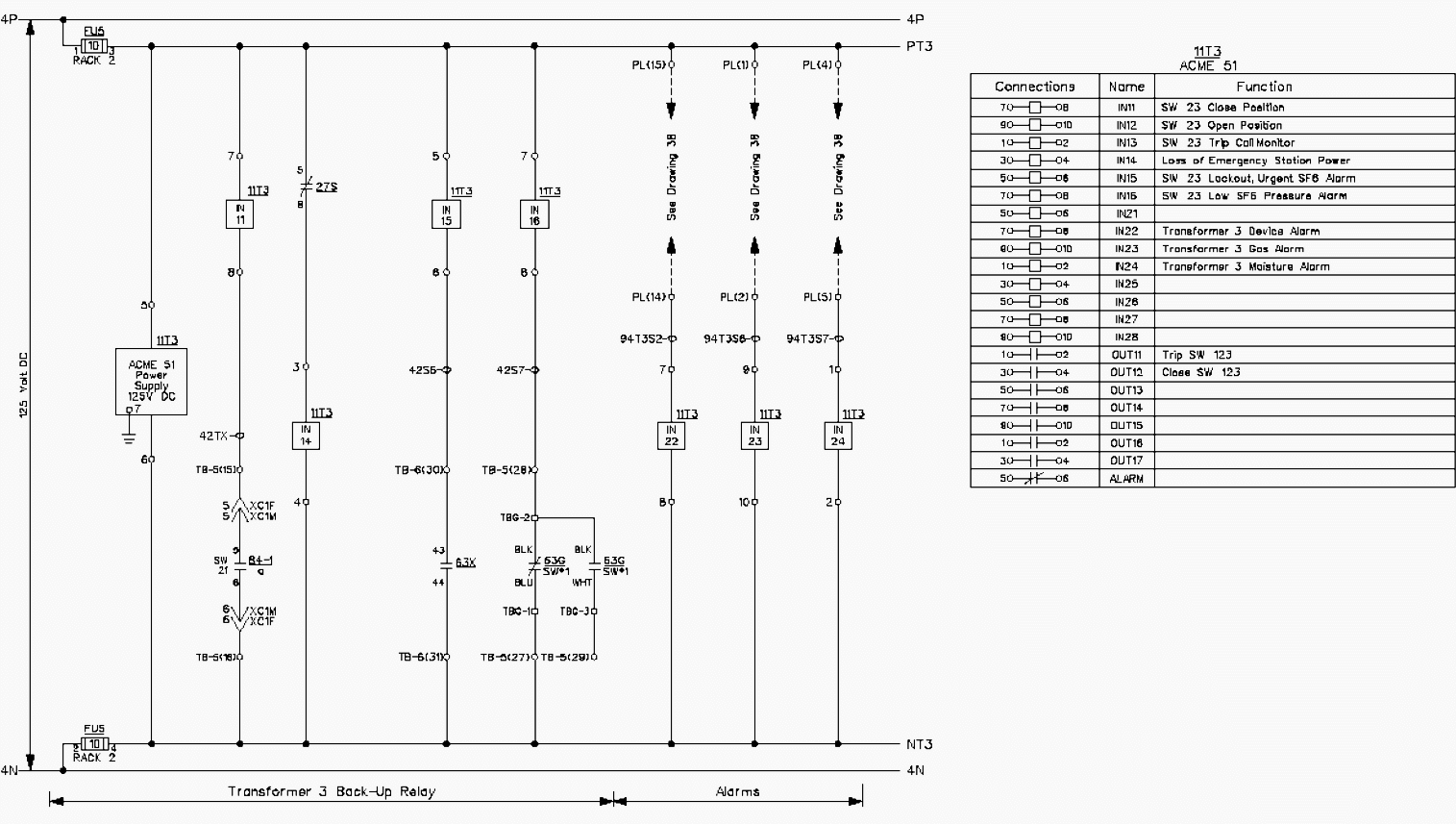
Reading And Understanding AC And DC Schematics In Protection And
 electrical-engineering-portal.com
Reading and Understanding AC and DC Schematics In Protection And ...
Ac To Dc Schematic Diagram
 www.circuitdiagram.co
Ac To Dc Schematic Diagram
Step-by-Step Design Guide | Upstate Door
 www.upstatedoor.com
Step-by-Step Design Guide | Upstate Door
Reading And Understanding AC And DC Schematics In Protection And
 electrical-engineering-portal.com
Reading and Understanding AC and DC Schematics In Protection And ...
How Does A Dc To Dc Converter Work - Design Talk
 design.udlvirtual.edu.pe
How Does A Dc To Dc Converter Work - Design Talk
Multimeter Schematic Diagram
 www.circuitdiagram.co
Multimeter Schematic Diagram
Dc To Ac Circuit Diagram Inverter
 circuitzemljam1jq.z21.web.core.windows.net
Dc To Ac Circuit Diagram Inverter
12v Ac To Dc Converter Circuit Diagram
 schematicdbfixagea55.z21.web.core.windows.net
12v Ac To Dc Converter Circuit Diagram
Backlit Mirror Step-By-Step Design Guide – Glazonoid
 www.glazonoid.com
Backlit Mirror Step-By-Step Design Guide – Glazonoid
Ac To Dc Converter Circuit Diagram With Transformer - Wiring Digital
 www.wiringdigital.com
Ac To Dc Converter Circuit Diagram With Transformer - Wiring Digital ...
Digital Peak Current Mode Control Step-by-Step Design Guide
 www.omicron-lab.com
Digital Peak Current Mode Control Step-by-Step Design Guide
Quasi Resonant Flyback Step By Step Design Guide | ElectronicsBeliever
 electronicsbeliever.com
Quasi Resonant Flyback Step by Step Design Guide | ElectronicsBeliever
Schematic Design Plans Schematic Design Phase Architecture
 mikuruzfcguidefix.z14.web.core.windows.net
Schematic Design Plans Schematic Design Phase Architecture
Reading And Understanding AC And DC Schematics In Protection And
 electrical-engineering-portal.com
Reading and Understanding AC and DC Schematics In Protection And ...
Inverter Schematic Diagram 12v To 220v 12v Inverter Circuit
 liturgia09d5glibguide.z14.web.core.windows.net
Inverter Schematic Diagram 12v To 220v 12v Inverter Circuit
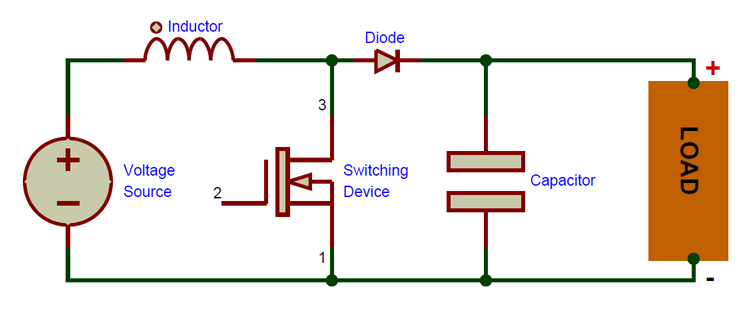
Boost Converter Schematic Diagram
 manualdiagramausterlitz.z19.web.core.windows.net
Boost Converter Schematic Diagram
Step By Step Design Step-cone Pulley In SOLIDWORKS - WizEdu
 wizedu.com
Step by step design step-cone pulley in SOLIDWORKS - WizEdu
Circuit Diagram Of Ac To Dc Converter Circuit Dc Ac Converte
 esikadew91guidefix.z13.web.core.windows.net
Circuit Diagram Of Ac To Dc Converter Circuit Dc Ac Converte
Reading And Understanding AC And DC Schematics In Protection And
 electrical-engineering-portal.com
Reading and Understanding AC and DC Schematics In Protection And ...
Mylar Bags Step By Step Design Guide Template – EPac
 epacflexibles.com
Mylar Bags Step By Step Design Guide Template – ePac
12v ac to dc converter circuit diagram. step by step design step-cone pulley in solidworks. Boost converter schematic diagram